Lilco logo 413x119

UK Design and manufacture of wideband current measurement transformers and wideband voltage measurement transformers

INTRODUCTION

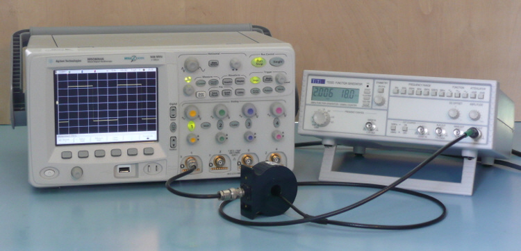
Lilco CT pulse 02_750x362

Current measurement with electrical isolation

The principal advantage of using current transformers to measure currents in electric circuits is that the measurement circuit can be electrically isolated from the circuit under test. This non-contact approach to current measurement greatly facilitates the simultaneous measurement of current and voltage in different branches of a common circuit. Isolation can be a particular benefit where high voltages are present.

Negligible Burden
Current transformers impose a negligible burden  on the circuit under investigation and their use has an insignificant effect on the performance of the circuits examined
 

Lowfrequ

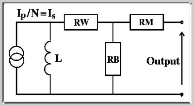
Low frequency equivalent circuit

Passive Device
They are passive devices.   Their ability to operate without a power source facilitates their permanent installation in equipment and avoids distortion that could be introduced by electronic amplifiers.
 

Is represents the secondary current given by Ip/N where Ip is the primary current and N the turns ration
RW is the resistance of the secondary winding
RB is the transformer burden
L is the inductance of the secondary winding
RM is the HF matching resistor

In its basic form the transformer consists of a toroidal core with a wound secondary which is shunted by a resistor of low inductance. In the terminated model, this resistor is supplied within the case of the transformer. In ring-type models the customer supplies the resistor RB. The primary is made when the conductor is placed through the aperture by the user. No direct connection exists between the primary and secondary electrical circuits. The simplified transformer equivalent circuit is helpful in understanding the operation of the instrument.

The Core is selected to have negligible losses under its operating conditions.    The winding resistance can have an important effect on the low-frequency cut-off point, though its effect over the major part of the instrument's operating range may be ignored. Current flowing in the primary winding induces a current in the secondary circuit. The current flowing in the load resistor is much lower than the primary current because of transformer action. Over the operating range, the output voltage is the product of Is and RB and is therefore proportional to primary current.
 

The matching resistor is used to match the output impedance to 50 ohms. The output resistance of the broadband internally-terminated instruments is matched at the time of manufacture. The matching resistor may not be required at the lower operating frequencies of the ring-type transformers. The toroidal structure maximises the magnetic efficiency and reduces electromagnetic pick-up.

The case of the terminated transformers forms an electrostatic screen. In the ring-type transformer the primary conductor should be screened if pick-up is likely to be problem

Further technical information on the operation of broadband current transformers may be found in: B. Cordingley, 1998, "Wideband Terminated Current Transformers for Power Electronic Measurements", Power Electronics and Variable Speed Drives, IEE Conf. Pub. No.456, pp 433-436.

Superior accuracy and hf response

The company supplies both terminated transformers and unterminated ring-type cts.    The terminated transformers have a superior accuracy and higher frequency response than other current transducers which operate on the principle of magnetic coupling, such as Rogowski coils and Hall-effect devices.

Accuracy is +/-0.5% over much of the operating range. Lilco terminated transformers are available with frequency responses in the range 0.1Hz to 100MHz.Ring-type transformers are supplied unterminated and are an economically-priced alternative to the terminated range of transformers for some duties. They are suitable for use in applications where the excellent high-frequency response of the terminated transformer is not required. Frequency response is in the range 0.1Hz to 2MHz. In low-current pcb-mounted models the upper frequency limit can be as high as 15MHz

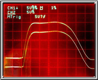
Upper trace: A transformer monitors the discharge of a pulse forming network by a fast-switching thyristor, 100A/div., 1us/div.

Lower trace: Same measurement but performed with an 0.1 ohm non-inductive shunt terminated for 0.05V/A or 100A/div. Notice should be taken of the fidelity of reproduction and the absence of phase error in the comparison.

Updated    December 2018

Trace